OSI Layers and Encapsulation
Follow one message down the sending stack and up the receiving stack. Explain the job at each layer and distinguish end-to-end information from a frame used on only one link.
Before you start
- Identify payload, header and trailer at the layer being counted.
- Distinguish a next-hop link address from the final network-layer destination.
Watch, pause, try
Video by Professor Messer. This general Professor Messer explanation develops the seven OSI layers. Pearson also requires the distinct TCP/IP model, supported by the primary Internet architecture reading. Treat OSI as a reference model; distinguish application-protocol behaviour from everything visible in a user interface and network packets from their link frames.
Viewing focus: Identify the seven OSI layers and their roles
After watching, attempt these questions before opening the answers. You can also use the written lesson below.
After watching 1: A supplied model has 1,400 application bytes, 20 TCP-header bytes, 20 IP-header bytes and 18 combined link-header/trailer bytes. Calculate counted frame size and application-payload percentage, excluding every other overhead. Which assumption would be wrong if this number were called a universal Internet frame cost?
Show answer and reasoning
The counted total is 1,458 bytes. Application payload fraction is 1,400/1,458=700/729, about 96.02%. Real headers, options, segmentation and physical overhead depend on the protocol/version and counting boundary. This calculation uses the supplied model; it does not make every application message one frame or establish a universal fixed overhead.
After watching 2: In a simple two-link A→router→D path with Ethernet links and no NAT, explain why the next outgoing frame can have different source/destination MAC addresses while the intended IP destination remains D. Does that mean every bit of the IP packet must remain unchanged?
Show answer and reasoning
The first link frame delivers from A’s interface towards the router’s incoming interface; the next uses the outgoing router interface and suitable next-hop destination on its link. Network-layer routing still targets D in this stated no-NAT model. That does not imply every packet field is unchanged: forwarding can update fields such as an IPv4 TTL and its related header check. Keep the logical destination, packet processing and link wrapper distinct.
What you'll be able to do
- Identify the seven OSI layers and their roles
- Trace encapsulation and decapsulation
- Calculate overhead under explicit header assumptions
Use the reference model to separate responsibilities
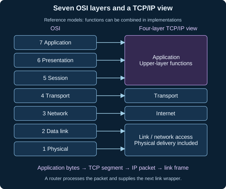
The OSI model describes seven layers, from application at the top to physical at the bottom. Application supports network application services; presentation concerns representations such as encoding; session concerns managing a dialogue; transport provides end-to-end transport services; network handles logical addressing/routing; data link handles communication over a link; and physical concerns transmitted signals.
It is a reference model, not a claim that every deployed protocol fits into one perfectly isolated box. Functions can be combined in actual software. For a diagram task, name the layer’s responsibility before assigning an example. An application-layer protocol is not the same thing as the entire user application, and reliable transport is a service choice rather than a property of every possible transport protocol.
Wrap the data, then remove the wrappers
Encapsulation adds protocol information as data move down a sending stack. In a common Internet example, application bytes become a TCP segment, carried inside an IP packet, carried inside a link frame and represented as physical signals. Decapsulation at the receiver interprets/removes the appropriate information and passes the payload upwards. The wrapper belongs to the protocol operating at that stage.
An intermediate router processes the incoming link delivery and the IP routing information, then sends a new frame appropriate to the next link. The next-hop link addresses can differ from the previous link’s. Do not assume one Ethernet frame travels unchanged across the whole Internet. End-to-end addresses/ports also need qualification when mechanisms such as NAT are involved; state the simple model used in the trace.
Count only the supplied overhead
Assume 1000 application bytes, a 20-byte TCP header, 20-byte IP header, 14-byte link header and four-byte link trailer, with no other overhead. The model sends 1058 bytes at the counted link-frame level. Its application payload fraction is 1000/1058≈94.52%. Physical preambles, gaps, options and other protocols are deliberately outside this model.
This example separates payload size from transmitted size. Headers vary by protocol, options and version, so do not memorise the example’s sum as a universal overhead. Similarly, one application message can require several transport segments or share a stream with other messages. Label the unit being counted and the endpoints of the comparison before calculating efficiency or transmission time.
| OSI layer, top→bottom | Principal responsibility in this model |
|---|---|
| 7 Application | Network application services |
| 6 Presentation | Representation/encoding-related functions |
| 5 Session | Dialogue/session coordination |
| 4 Transport | End-to-end transport service |
| 3 Network | Logical addressing and routing |
| 2 Data link | Frames and delivery over a link |
| 1 Physical | Signals over the medium |
Work through the problem
Attempt the task before opening its worked response. Record each change of state, explain the rule used, and check the result against the original requirements. Code examples labelled Python 3 use that language’s conventions; pseudocode states its own assumptions.
Example 1Calculate counted frame size and application fraction under the stated header model.
Example 2Why is a router’s next outgoing frame not necessarily identical to the incoming frame?
Common mistakes to avoid
Key takeaways
- The seven-layer reference model separates responsibilities.
- Encapsulation wraps payloads and decapsulation interprets them.
- Overhead and hop behaviour require an explicit protocol model.
Explore further
- Pearson YCP01 official specification (opens in a new tab)
Check the International A-level requirements and relevant numbered points; this course remains in progress.
- Pearson International Computer Science subject guide (opens in a new tab)
Official introduction to the four examined units and their theory/practical purposes.
- Topic reading and reference (opens in a new tab)
Use the relevant board requirement or primary technical reference alongside the written examples.
- Understanding the OSI Model - CompTIA Network+ N10-009 - 1.1 — Professor Messer (opens in a new tab)
Original publisher or creator source for the embedded explanation; apply the stated viewing scope.
Return to this tomorrow
Close the notes and answer from memory. Revisit any explanation you cannot yet reconstruct.
- An Ethernet frame must remain unchanged across every Internet hop:
- The overhead calculated here is:
Test yourself
Answer a few questions, then review anything you missed.
Keep practising
Start with the quiz above to check the key ideas. You can also choose another topic from the practice library.
Related lessons
All 4 lessons- Same chapterTCP/IP and a TLS HandshakeCompare the four-layer TCP/IP model with OSI
- Same chapterPacket Switching and Next-hop RoutingExplain packet components and store-and-forward decisions
- Same chapterDNS Hierarchy, Resolvers and CachingDistinguish client, recursive resolver and authoritative servers