Loading...
11.1.1Advanced Systems and RepresentationCore
Harvard and von Neumann Memory Paths
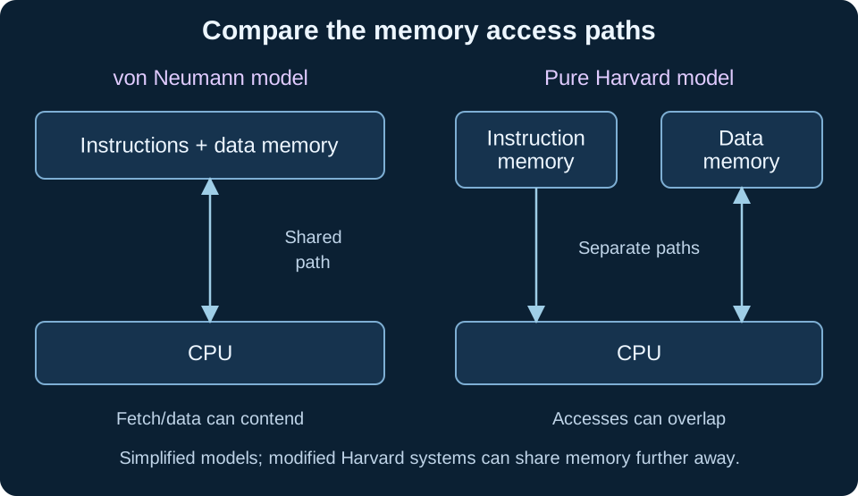
Compare the paths an instruction and its data take to reach the processor. A useful architecture diagram names memories and buses and connects the organisation to possible access contention.
What you'll be able to do
- Complete Harvard and von Neumann block diagrams
- Explain shared-path contention and separate-memory access
- Evaluate benefits and limitations without overgeneralising real CPUs
1
Revisit the shared-memory model
In the simplified von Neumann model, instructions and data share a memory system and its access path to the CPU. The stored-program concept allows instructions to be represented in memory rather than fixed only by physical wiring. The control unit fetches instruction information and coordinates execution; the ALU performs arithmetic and logical operations, while registers hold immediate working state.
A single shared path can create contention when an instruction fetch and a data access both need it at the same time. This contributes to the von Neumann bottleneck. The problem concerns movement of instructions/data relative to processing demand; merely increasing a processor’s arithmetic speed does not guarantee that memory can supply work proportionally faster. Caches and other implementation techniques can reduce particular delays without changing every aspect of the abstract model.
2
Draw the Harvard separation
A pure Harvard architecture has separate instruction and data memories with separate access paths. Draw an instruction memory connected to the CPU’s instruction-fetch/control side and a data memory connected to its data-processing side. Label the paths so the diagram does not accidentally show two boxes feeding the same single shared bus.
With suitable separate resources, an instruction fetch and a data-memory access can occur concurrently rather than contend for one shared path. Instruction and data memory can also have different widths or implementation characteristics. This can suit an embedded design with program instructions in non-volatile storage and changing data in RAM. The organisation does not mean that either memory has unlimited bandwidth or that every instruction finishes in one tick.
3
Evaluate flexibility and actual implementation
Separate memories and buses add design resources and can complicate moving information between the instruction and data spaces. A shared-memory design can offer a unified address space and flexible use of capacity. Explain the required trade-off for the scenario: a fixed control program and a general-purpose workload may value different properties. Neither label alone determines performance, power use or application suitability.
Modern systems often use modified Harvard arrangements, such as separate instruction/data caches near the CPU with a shared memory system further away. Recognising that possibility prevents a misleading all-or-nothing claim. For an examination diagram, follow the model explicitly requested and use the appendix’s component/bus notation. A real implementation example should not be used to erase the distinction that the simplified diagrams are intended to teach.
| Question | von Neumann model | Pure Harvard model |
|---|---|---|
| Where are instructions/data? | Shared memory system | Separate instruction/data memories |
| Which access path? | Shared in the simplified comparison | Separate instruction/data paths |
| Possible contention | Fetch and data access may compete | Separate paths can overlap accesses |
| Trade-off | Unified capacity/addressing can be flexible | Separation adds resources and access distinctions |
4
Work through the problem
Attempt the task before opening its worked response. Record each change of state, explain the rule used, and check the result against the original requirements. Code examples labelled Python 3 use that language’s conventions; pseudocode states its own assumptions.
Example 1A diagram labels two memories Harvard but connects both through one exclusive shared access path. What needs clarification?
1Harvard’s defining comparison includes separate instruction and data access paths.
2Two differently named boxes alone do not demonstrate concurrent independent access.
3Draw and label the intended buses and explain any shared resource.
AnswerCorrect or qualify the access paths rather than relying only on the memory labels.
Example 2Why might separate non-volatile instruction storage and RAM suit a small embedded controller?
1The stable firmware and changing working data have different persistence needs.
2Separate memories/access paths can fit those roles and permit appropriate overlap.
3Power, capacity and interface complexity still need evaluation.
AnswerThe organisation matches distinct program/data roles; it does not guarantee universal performance superiority.
Common mistakes to avoid
Showing separate memory labels while hiding a shared bottleneck.
Draw and label the actual instruction/data paths.
Treating a pure classroom model as a complete description of every modern processor.
State the abstraction and recognise modified arrangements.
Key takeaways
- The shared-path model can create instruction/data contention.
- Pure Harvard separates both memories and access paths.
- Evaluate separation and flexibility in the given design.
Test yourself
Answer a few questions, then review anything you missed.
Next step
Browse practice topicsKeep practising
Start with the quiz above to check the key ideas. You can also choose another topic from the practice library.